Machined Features: Types, Symbols & DFM Rules
Machined features are the named shapes and details that a machinist creates when cutting metal, plastic, or another solid material. They are the vocabulary of a mechanical drawing: a hole, a groove, a flat, a thread, or a radius that appears on a print and tells the shop exactly what geometry to produce. If you can read these features and understand their limits, you can move from a rough concept to a part that machines cleanly and costs less.
This article covers the common feature names, how they appear on drawings, and the design-for-manufacturing (DFM) rules that decide whether a feature is easy or expensive to cut.
What Are Machined Features?
Machined Features: Types, Symbols & DFM Rules - What Are Machined Features?.
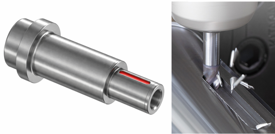
A machined feature is any surface or shape produced by removing material with a cutting tool. The term covers simple geometry such as a drilled hole or a milled slot, and more specific forms such as a counterbore, a keyway, or a spotface. On a drawing, each feature is usually defined by a combination of views, dimensions, notes, and sometimes a symbol.
The same feature can be made on different machines. A hole might be drilled on a mill or a lathe; a groove might be turned on a cylindrical part or milled into a flat face. The feature name describes the geometry, not the machine.
Common Types of Machined Features
The list below covers the features most often called out on industrial prints. Each entry explains what the feature is and where it is typically used.
Bevel
A bevel is a surface cut at an angle to an adjacent surface. In welding, a bevel often serves as edge preparation so the weld can penetrate fully. On a machined part, a bevel may be used to guide assembly or remove a sharp transition.
Boss
A boss is a circular pad that projects from a casting or forging. The top of the boss is usually machined flat so a bolt head can seat against it, and a hole is drilled through the center for the bolt shank. Because a boss is round by definition, a rectangular raised pad is called a pad instead.
Chamfer
A chamfer cuts away a sharp external corner or edge. It is commonly used to break edges, ease assembly, or protect a thread start. A chamfer is not the same as a bevel used for welding, although both are angled cuts.
Counterbore
A counterbore enlarges a drilled hole to a given diameter and depth. It creates a flat-bottomed recess so a bolt head or nut can sit below the surface. A counterbore is specified with both a diameter and a depth.
Countersink
A countersink cuts a conical depression into a drilled hole. It is used to recess flathead screws or bolts so the head sits flush with the surface. The angle is usually 82° or 90°, depending on the standard being followed.
Dovetail
A dovetail is a slot with angled sides. It can be any depth or width, and the angled walls allow it to act as a sliding joint or a locating feature.
Fillet
A fillet is a small radius that fills the inside angle between two surfaces. It reduces stress concentration and is often required where a machined surface meets an unmachined one.
Kerf
A kerf is the narrow slot left behind when material is removed by sawing or another cutting process. The width of the kerf depends on the tool, and it matters when you are planning how much material a cut will consume.
Keyway and Keyseat
A keyway is a groove cut into the bore of a hub or sleeve. A keyseat is a groove cut into a shaft. Both accommodate a key, which locks the two parts together so they rotate as one. The distinction matters because the feature is on different mating parts.
Knurl
Knurling roughens a cylindrical or flat surface with a diamond or straight pattern. It is used to improve grip or to increase the effective diameter of a press-fit section.
Lug
A lug is a projection from the body of a part, usually rectangular in cross section, with a hole or slot in it. Lugs are common on brackets and mounting points.
Neck
A neck is a narrow groove machined on a cylindrical part. It is often used to provide clearance for a tool or a mating component.
Pad
A pad is a slightly raised surface that projects from the body of a part. Unlike a boss, a pad can be any size or shape. The pad surface is often machined flat to provide a seating face.
Round
A round is a small radius on an outside corner between two surfaces. It softens the corner and reduces the chance of damage or injury.
Spline
A spline is a gear-like serrated surface on a shaft. It transmits torque and can replace a key when higher torque capacity is needed.
Spotface
A spotface is a round surface machined on a casting or forging so a bolt head can seat properly. It is usually shallow, often about 1/16 inch deep, and is used to clean up an uneven surface.
T-Slot
A T-slot is a slot shaped like a T. It is used for clamping, machine tables, and adjustable fixtures.
How Machined Features Appear on Drawings
Machined Features: Types, Symbols & DFM Rules - How Machined Features Appear on Drawings.
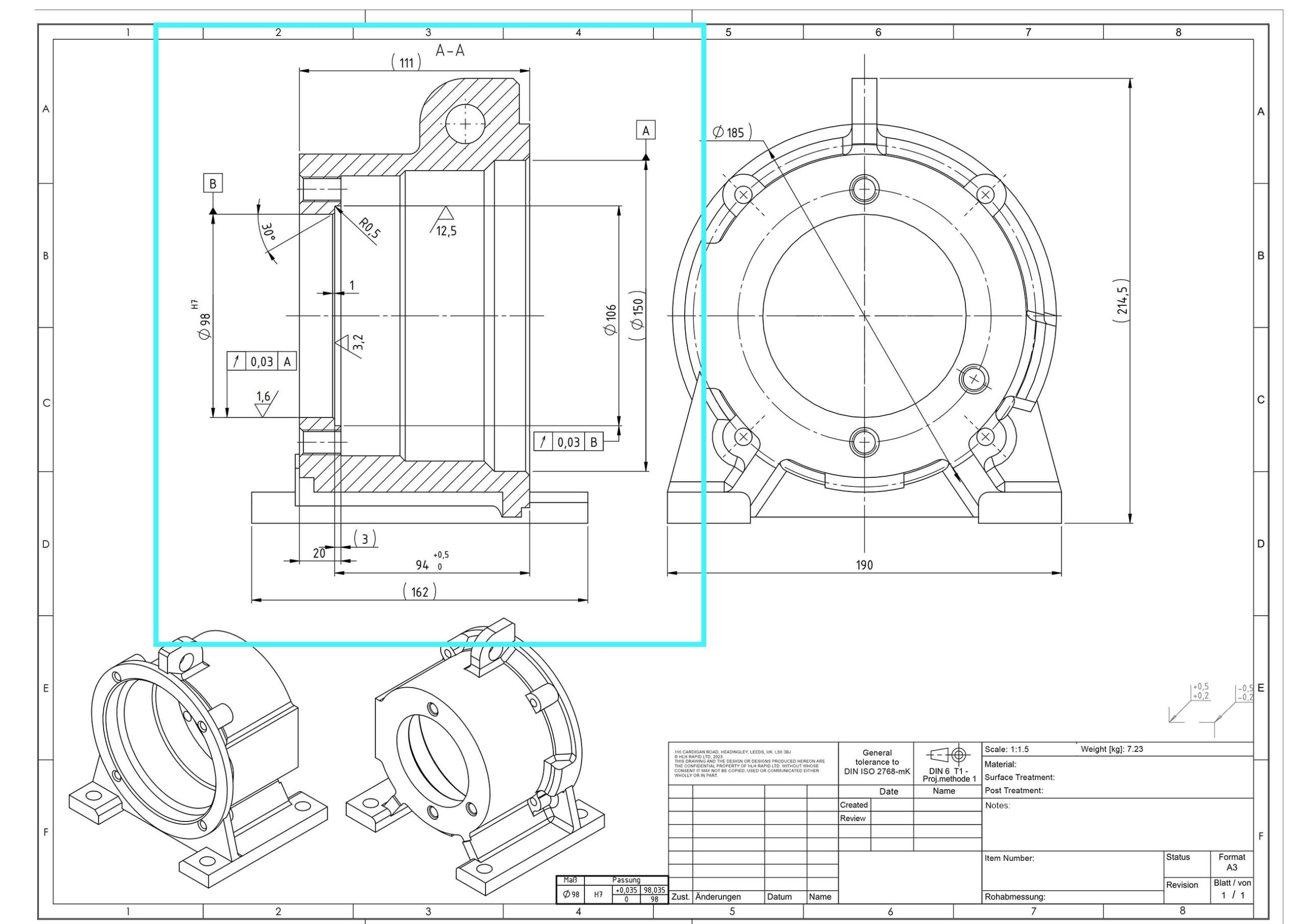
Machined features are communicated through a combination of views, dimensions, and notes. A hole may be shown in a section view with a diameter and a depth. A counterbore may be dimensioned with two diameters and a depth. A keyway may be shown in a section through the shaft or hub.
Symbols are also used. For example, a spotface or counterbore may be indicated with a symbol on a hole callout, and a countersink may be shown with an angle and a diameter. The exact symbol set depends on the drawing standard being used, such as ASME Y14.5 or ISO 1101. The important point is that the feature name and its dimensions must be unambiguous, because the machinist will build exactly what the drawing says.
If you are new to reading prints, a basic blueprint reading reference can help you connect the line work to the feature names. The Open Oregon blueprint reading chapter on machined features is a useful starting point for the vocabulary.
DFM Rules for Complex Machined Features
Machined Features: Types, Symbols & DFM Rules - DFM Rules for Complex Machined Features.
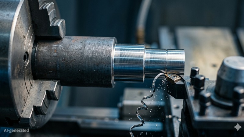
A feature that is easy to draw can be difficult to cut. The following rules come from real machining practice and are worth checking before you release a design.
Hole Depth and Diameter
On a lathe, on-axis and axial holes often have a minimum diameter around 0.04 in. (1 mm) and a maximum depth of about 6 times the diameter. Radial holes drilled from the side of the part are usually larger, often at least 0.08 in. (2 mm) in diameter. If a hole is too deep for its diameter, the tool may not reach, or the chips may not clear.
Deep Grooves and Slots
External grooves on a turned part have limits. One common guideline is that a groove cannot exceed about 0.95 in. (24.1 mm) in depth or be narrower than about 0.047 in. (1.2 mm). For milled slots, keep the depth less than about 6 times the feature width, and leave at least 0.020 in. (0.5 mm) of wall thickness on the adjacent material. These rules are not universal, but they reflect the stiffness and reach of typical cutting tools.
Threads
Threading capability depends on the machine and the feature placement. A typical automated shop can cut threads from #2-56 up to 1/2-20 in imperial sizes and from M1.6x0.35 up to M12x1.75 in metric sizes. If you need a thread in a soft material such as aluminum or plastic, consider a threaded insert. Coil inserts and key inserts provide longer service life than bare threads and are easier to replace if the thread is damaged.
Text and Engraving
Recessed text is one of the more time-consuming machining operations, and it becomes expensive as production quantities rise. If you need permanent marking, laser marking or electrochemical etching is usually more economical. If you must engrave, keep the text short and use a simple, clean font. For soft metals and plastics, a common recommendation is Arial Rounded MT at 14 point and 0.3 mm deep; for hard metals, Arial Rounded MT at 22 point and 0.3 mm deep.
Internal Corners and Radii
Sharp internal corners are a common mistake. A turning tool used for finishing may have a nose radius around 0.016 in. (0.4 mm), so any mating part should be designed with that in mind. Milling cutters can go down to about 0.040 in. (1 mm), which means a pocket will have an internal corner radius a little more than half that. Small tools take longer to run and are limited in depth, so it is better to relieve internal corners or allow the largest internal radius that the design can tolerate.
For a broader set of design tips on complex parts, Protolabs’ guide to mastering complex features on machined parts is a practical reference.
How to Choose and Specify Machined Features
When you specify a feature, you are also choosing a manufacturing process and a cost level. Use the following decision guidance to keep the design efficient.
- Use a standard feature when possible. A standard counterbore or a standard thread is easier to quote and inspect than a custom geometry.
- Match the feature to the process. A keyseat is usually cut on a shaft, while a keyway is cut in a hub. A spotface is used on a casting or forging, not on a clean machined face.
- Avoid unnecessary precision. A tight tolerance on a non-functional surface adds cost without adding value.
- Consider the tool reach. Deep pockets, narrow slots, and small internal radii all require long, thin tools that deflect and wear.
- Think about assembly. Chamfers and rounds help parts go together; sharp corners can cause interference or injury.
- Check the quantity. A feature that is acceptable on a prototype may be prohibitive in production. Text engraving is a classic example.
If you are comparing feature types, a simple rule is this: if the feature exists to locate, fasten, seal, or transmit torque, specify it precisely. If it exists only for appearance, specify it loosely or remove it.
Where Machined Features Fit in a Content Workflow
Engineering teams often document machined features in design guides, DFM checklists, and part libraries. Those documents are valuable, but they are also the kind of content that goes stale when a standard changes or a shop updates its capabilities. A content platform such as AgentBooks can help a manufacturing or SaaS team keep this reference material current by turning a website into an always-on content engine. AgentBooks learns the product, maps the market, plans topics, and publishes useful articles in the brand’s voice, which is useful when you need to maintain a library of technical explainers without rebuilding the workflow each time. You can read more about how it fits into a bulk article creation workflow or how to build topic clusters that rank around core engineering terms.
Related reading
- GEO Optimization: How to Get Cited by AI Search Engines - GEO optimization explained: how generative engines pick sources, what to fix on your site, and how to measure AI citations without abandoning SEO.
- ContentBot.ai Tutorial: Build AI Content Workflows - A hands-on ContentBot.ai tutorial: set up your account, build AI workflows, import CSV files, generate SEO content, and fix common mistakes.
- Solo Founder Marketing: A Lean System That Actually Works - A practical solo founder marketing system: pick one channel, batch content, use AI as a multiplier, and track the few metrics that matter.
Sources and further reading
- Nomenclature for types of machined features : r/AskEngineers - Reddit - Feb 20, 2024 ... Comments Section ... side milling and slotting are the operations you describe. ... I don't think this is quite what you are looking for, but I'll ...
FAQ
What is the difference between a counterbore and a countersink?
A counterbore creates a flat-bottomed recess for a bolt head or nut. A countersink creates a conical depression for a flathead screw or bolt. The counterbore is defined by a diameter and depth; the countersink is defined by a diameter and an angle.
What is the difference between a keyway and a keyseat?
A keyway is cut into the bore of a hub or sleeve. A keyseat is cut into a shaft. Both hold a key that locks the two parts together.
What is a spotface used for?
A spotface machines a round, shallow surface on a casting or forging so a bolt head can seat flat. It is usually about 1/16 inch deep and is used to clean up an uneven surface.
Why are sharp internal corners a problem in machining?
A cutting tool has a radius, so it cannot cut a perfectly sharp internal corner. If the drawing calls for a sharp corner, the shop must use a smaller tool or add a relief, which increases time and cost. Designing a realistic internal radius avoids the problem.
How deep can a machined hole be?
A common rule is to keep the depth no more than about 6 times the diameter. Deeper holes require special tooling and are more likely to drift or break the drill.
Conclusion
Machined features are the shared language between design and manufacturing. Knowing the names, the symbols, and the DFM limits helps you create drawings that are clear, buildable, and cost-effective. Start with standard features, respect tool reach and corner radii, and document the result so your team can reuse it. Whether you are reading a blueprint for the first time or refining a complex part, the same principle applies: the clearer the feature definition, the smoother the path from print to part.